
Backstory:
Some time ago I visited a Value World, a sort of thrift store, to browse what they had in stock. These kinds of stores may appear trashy because they stock items that people no longer want anymore. However, they also can contain "treasures". You know the old saying, right? One man's trash is another man's treasure? So, anyway, I came across two identical toy RC cars. One was in much better cosmetic condition than the other but they both appeared to be intact. As I was looking them over I noticed that they did not include the battery pack or the remote control for the cars. I knew right then that they would probably never sell because who in their right mind would purchase a toy RC car without the batteries and the remote? Me... Ha! I knew how to convert the power from battery packs to other voltages (regulators) and I knew about how to replace the analog potentiometers in a remote with digital ones so that I could control the car with a micro-controller. I wanted a challenge because this time I couldn't just control the remote. This time I would need to tap into the existing electronics of the car. I purchased both cars for less than $5. I also found a Playstation driving wheel and pedals which may potentially be part of this project.
What is it going to take?:
This project required me to basically reverse-engineer a printed circuit that utilized an IC chip that I could not find a datasheet for. If I had found a datasheet for that chip then the task would have been so much more simple. But, I had to make due with what I had. The car was a "Tyco Speed Wrench", a typical toy RC car with controls for Forward, Backward, Left, Right and Turbo. Basically, the unknown IC chip would handle signals from the radio receiver and then act accordingly by putting a signal on the proper output pins. THIS was my task.
Reverse-engineering the circuit: Drive Controls:
First, lets take a look at the top of the circuit. Please note that the top picture is horizontally flipped so that it was easier to compare pictures of the front and back of the circuit.
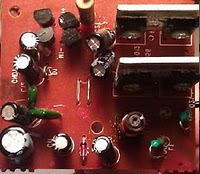 * * | On the right side you can see the drive transistors. I believed that this is an H-bridge configuration and assumed that Forwards and Backwards would use separate pairs of these transistors. There were two each of the following transistors: 2SB1658 which handled negative voltage and the 2SD22583 which handled positive voltage. Understanding transistors, I knew that my task would require me to identify the "bases" of each transistor and then trace back through the circuit to find the pins on the IC that controlled the Forward and Backward drive. |
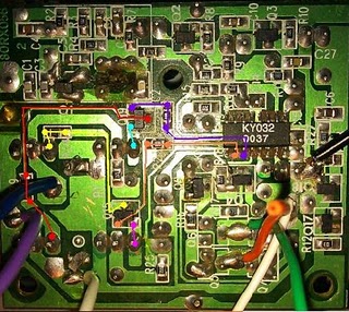 * * | At first, I thought that this would be as easy as using a continuity tester from the base of each transistor to all the pins on the IC but this did not work because there was additional circuitry between the bases and the IC. Specifically, an additional transistor and resistor for the Forward and Backward function. This task could have been very annoying and time-consuming but I came up with a great idea. I took a picture of the bottom of the circuit then loaded it up on my computer and enlarged the picture. Then, with my continuity tester I would check along the circuit paths and then draw the circuit paths using different colors on the picture of the circuit that I took. (This picture can be clicked on and expanded.) |
After I determined how the circuit worked, it was time for me to try to slice into it. I quickly wrote a simple Arduino program that would send 1/4 of the full on voltage (5V) via PWM to one of the Drive pins on the IC. At this point, I knew which pins they were but I did not know which pin of those two pins was going to be Forward and which pin was going to be Backwards, so this next part was going to be a surprise! (Man, that sure sounded nerdy didn't it?) Anyways, the program would loop with a pulse of the pin ON for a second and then OFF for a second. Results? Wheels-are-a-turnin', in reverse BTW. I tested the other pin in the circuit and it was Forward. Now that I have "Learned how to drive," the next step is to learn how to steer.
Reverse-engineering the circuit: Steering Control:
This time it was another two types of transistors with 2 of each. This consisted of the 8050 and the 8550 transistors. I assumed that this 4 transistor configuration was doing something similar to what was being done for the drive transistors but at a much lower power. I was able to find the datasheets on both transistors and the only difference that I immediately found was that the 8550 was PNP and the 8050 was an NPN. Again, I found the bases (which were the middle pin of the transistor) and traced the circuit to find how which pins of the control chip controlled the steering motor.
Putting it all together:
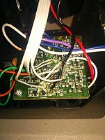
Now that I knew which pins of the IC controlled the drive and the steering, it was time to put everything together. As I said earlier, I was lucky to be able to purchase 2 identical RC cars. Up to this point I had only been working on the more worn-looking one. It was now time to take everything that I have learned and modify the newer-looking car and create the end product.  * * | First I removed the top of the car which was holding down two sections. Then I opened up the section that contained the circuitry. Although this isn’t important, I took notice of how much more shinny this board was than the one that I was working on. |
Now that I had access to the circuit board it was time to make the modifications. I used some ribbon cable that is used for old floppy drives. This cable is thin and flat as well as easy to fold. I stripped the ends of of each of the 5 wires of the ribbon cable that I cut. The wires would be soldered to the beginning of the sections of the board for Forward, Backward drive and left and right steering. The 5th wire I soldered to ground. I did this because when you control one circuit with another, you need to connect the grounds otherwise the signals do not go through. I used hot glue to seal the soldering.
|  * * |
 * * | I then put the car back together. The back of this car resembles a sort of pick-up truck. Underneath the "pick-up" lid I was able to re-purpose the original bay that held the battery. As I was using a different battery type I soldered on a female connector for the battery type that I intended to use. I soldered right to the original contacts. I then replaced the lid of the “trunk” and placed my micro-controller and other supporting gear on top of it. The original design was fastened down with just a rubber-band. |
The ribbon cable I used was of the stranded type and I could not plug in those wires into my Arduino I/O ports. To solve this problem I soldered solid-core wire to the ends of the wires. Each wire was given a different color.
|  * * |
Last, I put my old G1 Android cell phone on the front bumper, connected it to my home WiFi and installed the IP Webcam program. Now, I can drive the car while I am not in the same room by watching the video feed on my computer. (I have included a video of this.)
The Results:
I finally had the modifications to my car complete. Now I needed some way of controlling it. In previous projects, including the original “Super Car”, I utilized a wireless PS2 Gamepad for control. I decided to add in this functionality for control for this project too. The code for this RC Car is relatively simple. It simply polls the PS2 gamepad and then acts accordingly. I decided to use the analog sticks for drive and steering and the green triangle button for the horn which I added in later. I have made this code available for download. You will also need Bill Porter’s PS2 library as well. The excellent work that Bill Porter put into creating a complete and very usable Arduino library for PS2 controllers was very helpful. I tried to create my own but his was already complete and he updates it if bugs are discovered. A link to his website will be in the reference section of this post.
Here is a picture of the back of the car and the Car Car video. Please leave comments if you have any questions or ideas! Oh, and the code that I wrote for the car control is also available below!


No comments:
Post a Comment
Keep it clean. :)